Parity in data storage systems is a computational technique to check for data losses and overwritten data during transmission from one storage device to another. It also checks for errors during the operation and corrects them.
To ensure error-free data transmission, a parity bit is added to the dataset (bits) that are being moved. This bit adds checksums into the data, which are used by the target device to identify and determine the accuracy of the data received.
RAID configurations, like RAID 5 and RAID 6, use a type of parity, known as distributed parity, which ensures fault tolerance and data redundancy. Fault tolerance adds resilience to the array, which enables it to sustain disks failure (e.g. RAID 5 can sustain 1 disk failure and RAID 6 can sustain 2 disks failure), thus preventing unprecedented data loss.
How Data Parity Works in RAID?
Parity is a common way to deal with unprecedented data loss in certain RAID configurations, like RAID 5 and RAID 6. It is a component that is calculated and either stored in a dedicated disk or distributed across the drives in the array. This provides protection against complete array failure.
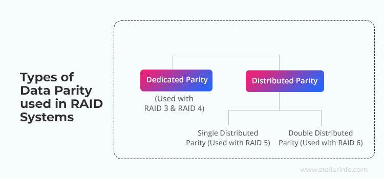
Standard RAID levels, such as RAID 3, RAID 4, RAID 5, and RAID 6 employ data striping and parity. In the case of RAID 3 and RAID 4, data is striped across the member drives. They use a dedicated parity, which is calculated and stored on a single parity drive. RAID 5 and RAID 6, on the other hand, stripe data across the member drives. It uses distributed parity that is calculated and distributed across the member drives.
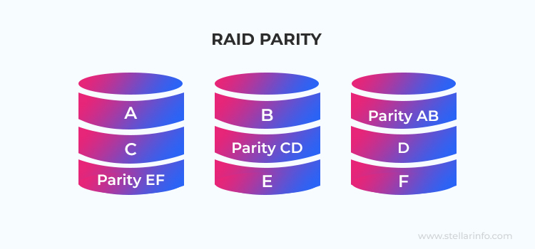
Here is a diagrammatic representation of various types of data parity used with different RAID configurations.
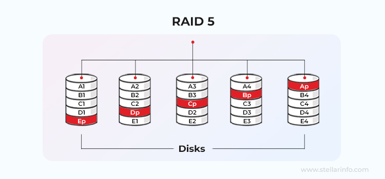
RAID 5 is a block-interleaved distributed parity disk array that requires a minimum of 3 member drives to configure. This configuration combines data striping and parity to offer a balanced solution for users looking for data availability and fault tolerance. Fault tolerance is achieved using single distributed parity, which is calculated using the XOR function and spread across all member drives. This enables the array to sustain a single drive failure.
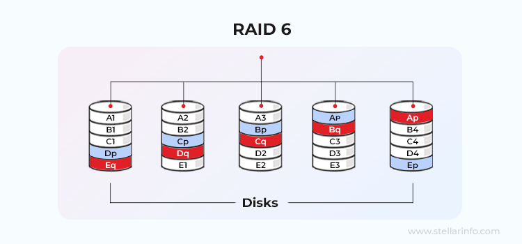
RAID 6 is built upon the same concepts as RAID 5 and uses block-level data striping with double-distributed parity spread across the member drives. RAID 6 offers improved data read speeds and an additional parity block, which lends it fault tolerance of up to two drives failure.
Parity Distribution in RAID
Depending upon the RAID controller, the purpose of RAID, and other factors, users can configure the member drives accordingly. Moreover, users can also select the type of parity distribution for simplicity and efficient I/O loads.
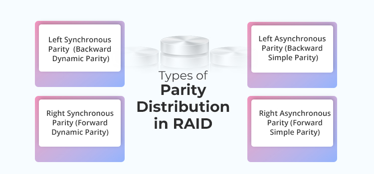
There are four kinds of parity distributions:
- Left Synchronous Parity (Backward Dynamic Parity)
- Right Synchronous Parity (Forward Dynamic Parity)
- Left Asynchronous Parity (Backward Simple Parity)
- Right Asynchronous Parity (Forward Simple Parity)
Calculation of Distributed Data Parity in RAID Array
Here, we will understand how parity is calculated and stored in RAID. We will be taking RAID 5 and RAID 6 arrays as examples to demonstrate the process.
Data Parity in RAID 5
RAID 5 uses a simple Boolean operation or a logical gate called the XOR or Exclusive Disjunction operation, or Exclusive OR gate to calculate parity. This logic gate works at a binary level by passing binary data through the operator and producing a binary result.
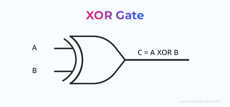
Here is the formula of the XOR gate: Input 1 XOR Input 2 = Output
The output or the calculated parity is dependent on the binary data input through the gate. The XOR gate produces an output of “1” (HIGH/TRUE), if the input values are different and “0” (LOW/FALSE), if they are same.
However, the output of XOR gate is also a function of the number of HIGH/TRUE inputs. An odd number of HIGH/TRUE or “1” input will generate a HIGH/TRUE or “1” as an output, whereas an even number of HIGH/TRUE or “1” input will generate a LOW/FALSE or “0” as an output.
Let’s take a look at the truth table of the XOR gate to understand it better:
| Input 1 | Input 2 | Output |
|---|---|---|
| 0 | 0 | 0 |
| 0 | 1 | 1 |
| 1 | 0 | 1 |
| 1 | 1 | 1 |
Now, let’s understand how parity is calculated and how lost data is rebuilt using the XOR logic gate with the help of an example. Here, we have a RAID 5 array with a 4-drive setup. We will be working with the following data bits stored in the first 3 drives:
|000|010|001|
| Drive 1 | Drive 2 | Drive 3 |
|---|---|---|
| 0 | 0 | 0 |
| 0 | 1 | 0 |
| 0 | 0 | 1 |
Now, if we calculate the XOR of the three drives, we will get the parity on the fourth drive. This is how it looks:
| Drive 1 | Drive 2 | Drive 3 | Parity |
|---|---|---|---|
| 0 | 0 | 0 | 0 |
| 0 | 1 | 0 | 1 |
| 0 | 0 | 1 | 1 |
Now that we have calculated the parity, let’s see how it helps recalculate the data in case of a drive failure. Let’s assume the third drive of the array has failed. This is how the array will look:
|000|010|001|011|
The highlighted data bits above suggest that the drive has failed. Now, we will use the bits from the remaining drives and the parity stored in the fourth drive. If we calculate the XOR of the remaining bits, it will return the missing bits (data) of the third drive:
| Drive 1 | Drive 2 | Parity | Drive 3 (Rebuilt) |
|---|---|---|---|
| 0 | 0 | 0 | 0 |
| 0 | 1 | 1 | 0 |
| 0 | 0 | 1 | 1 |
This is a simple demonstration of how the XOR logic gate works in RAID 5 using 3 bits. You can follow the steps above to recover data bits of any failed drive. However, in real scenarios, RAID 5 works on a large number of bits, which depends upon the strip size.
Data Parity in RAID 6
Unlike RAID 5, which uses a single parity block, RAID 6 uses two parity blocks. This gives it fault tolerance of two drives failure, which allows it to sustain two arbitrary drive failures without data loss. While this helps it to be more resilient, it increases the complexity of parity calculation during the setup and data recalculation in case of drive failure.
The first parity block of RAID 6 is calculated using the XOR logic gate (similar to RAID 5). The second parity block contains Reed-Solomon Codes (RS Codes) that are calculated with the help of complex mathematical operations.
According to the research paper – A Tutorial on Reed-Solomon Coding for Fault-Tolerance in RAID-like Systems published at the University of Tennessee, “There are three main aspects of the RS-Raid algorithm: using the Vandermonde matrix to calculate and maintain checksum words, using Gaussian Elimination to recover from failures, and using Galois Fields to perform arithmetic.”
Here is a table showing the parity calculation and other details of RAID 5 and RAID 6 arrays:
| Type of RAID Configuration | Min. No. of Drives Required | Type of Parity | Fault Tolerance | Parity Calculation Method |
|---|---|---|---|---|
| RAID 5 | 3 | Single distributed | 1 drive failure | XOR logic gate |
| RAID 6 | 4 | Double-distributed | 2 drive failure | XOR logic gate + RS code |
Recovering Data from a Failed RAID Array
Fault tolerance in RAID 5 or RAID 6 array plays an important part in recovering data from a failed array. If the disk failure is within the permissible limits, you can hot swap the failed disk drive with a healthy one and rebuild the array.
At times, simultaneous member drive failure is possible during RAID array rebuild, which can cause the RAID rebuilding process to be halted. Therefore, ensure that you inspect the health of the other drives prior to that.
Additionally, such interruptions as abrupt loss of power, power surges, etc., during RAID rebuild can cause corrupted RAID configuration, which may bring about disastrous data loss.
To ease the recovery process of data from a failed RAID 5 or RAID 6 array, you may use Stellar Data Recovery Technician. It is a powerful RAID data recovery tool that can recover data from a failed RAID 0, 5, 6, or hybrid RAID array lost due to circumstances such as accidental deletion, corruption, partition formatting, incorrect RAID rebuild, etc.
The software scans the member drives of the failed RAID array comprehensively, makes a virtual image based on multiple RAID parameters, and recovers the data afterward. The software is also equipped with a built-in drive monitor that allows you to verify the health of member drives.
Conclusion
Advanced data storage solutions, like RAID 5 and RAID 6, leverage parity as it ensures data integrity and provides resilience. If the drive failure is within the permissible limits, parity can be used to recover lost data from the RAID without any challenges.
However, rebuilding a failed RAID array comes with its own set of challenges. It is a time-consuming and complicated process. Alternatively, you can use a specialized RAID data recovery software, like Stellar Data Recovery Technician, to streamline the process. The software simplifies the data recovery process from a failed RAID array by virtually reconstructing the array, scanning the drives for lost data, and then recovering it.
Related Reads
All You Need to Know About RAID Arrays


A passionate writer driven by his interest in everything tech, Keshav Katyal has always been captivated by the latest gadgets since childhood. His interest in technology grew when he got his first gaming console, the Nintendo Game Boy Advanced.
 5 min read